The TIA (Television Interface Adaptor)
If you are not interested in detailed technical information about how the TIA works, but do want to understand how the Atari 2600 draws screens and how this influenced how the games were developed you may want to skim over this document and then play with the TIAEditor linked to at the bottom of this page.
As video is a very important, possibly the most important, part of a video game, understanding how the graphics for the display are generated is going to be something you want to focus on. Being one of the earliest consoles on the market, the 2600 does things a lot different than later consoles do. Most consoles actually have some type of graphics memory where the frame to be displayed is stored. The 2600, on the other hand, actually draws the display as the television is drawing the frame.

Back when the 2600 was released, televisions used what today we call standard definition. This was transmitted using a standard called the NTSC and was an analog signal. The televisions at the time used magnets to control a cathode ray that was used to draw the screen. The cathode ray excites a phosphorous coating on the screen causing it to glow briefly. This beam moves left to right from top to bottom drawing one scan-line at a time until a frame is completed, then is moved back to the top to repeat.
The Atari 2600 graphics are programmed by writing to TIA registers which are mapped to memory addresses. All the information here was obtained by reading the public domain Stella Programming Guide 1 which is extremely technical but still a must-have reference for anybody serious about Atari 2600 programming.
The Atari 2600 requires the programmer to actually render the graphics for the game a scan-line at a time as the TV is displaying it. The television standard at the time of the Atari 2600 was NTSC in North America. The TV starts with a Vertical Blank/sync period which is the time when the cathode beam is turned off and returned to the top of the screen. This lasts for 40 scan-lines which gives the game time to perform its game logic before having to do any rendering. Next each scan line gets drawn. Finally, there is what is called an overscan period. These are lines at the bottom of the screen which may not be seen so the final 30 scan-lines are not used and the waiting time can be used for additional game logic.
The TIA uses it's own timer, referred to in the Stella documentation as the clock which is 3 times the speed of the CPU. Each scan-line takes 228 clock ticks to draw. The first 68 being horizontal blank time, which is the time it takes the cathode to return from the far right of the screen back to the left. The next 160 ticks are used to draw the display. This effectively makes the resolution 160x192 but as the pixels are roughly twice as wide as they are tall it is best to think of the machine as having a 320x192 resolution or as having a 160x96 resolution if you are doubling up scan-lines to gain 152 CPU cycles per "line" instead of the 76 cycles.
Colours

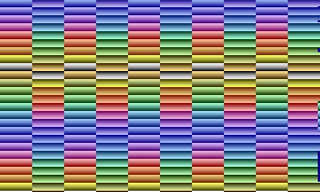
Each scan-line can have four colours. As you can change the colours in the middle of the scan-line you can actually get slightly more than this, but the number of cycles to change a register is at least 5 CPU cycles, which is 15 color-clocks, this is not very effective. The 4 registers used to control this are (note, I am using the 6502 $## format for hexadecimal numbers):
- COLUP0 ($06) - Player 1 sprite/missile colour
- COLUP1 ($07) - Player 2 sprite/missile colour
- COLUPF ($08) - Play field colour
- COLUBK ($09) - background colour
Play fields
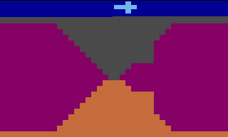
The play field graphics are for creating the mazes and other background images for games. A play field block is 4 clock ticks wide, with 20 of them making up half of the screen. The other half of the screen is either a mirror or a duplicate of the first half. As only 3 registers need to be set to control all 20 blocks, it is actually fairly easy to alter the play field data half-way through the scan-line to create asymmetrical play fields. Unfortunately, the bits in these bytes are are not ordered in a normal way as simplifying the hardware was more important than ease of programming. If you consider bit 7 to be the leftmost bit, and bit 0 to be the rightmost bit, then PF1 is correctly ordered while PF0 and PF2 are in reverse order. The three play field registers are:
- PF0 ($0D) - Play field 0, drawing order: bits 4..7
- PF1 ($0E) - Play field 0, drawing order: bits 7..0
- PF2 ($0F) - Play field 0, drawing order: bits 0..7
Sprites

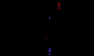
When it comes to what is currently called sprites, the 2600 was rather limited. It supported 2 player sprites, 2 missile sprites, and a ball sprite. Each treated separately. It is possible to appear to have more than these by repositioning a sprite after it has been drawn or (as was seen in the Pac Man port) drawing different sprites in different frames causing some flickering. Sprites were not positioned using an X coordinate, but instead were set using an offset register and a strobe register, making placing sprites rather complicated. Sprites are the length of the screen with the visibility and bit data (only the two player sprites have bit data, the other sprites are solid blocks) being controlled on a per-scan-line basis.
Player Sprites
As these give you 8 bits these are useful for adding fine detail to an image, but with only two of them this is very limited. The following registers are used for Player 0:
- NUMSIZ0 ($03) - Number and size of sprite
- REFP0 ($0B) - Reflect sprite (draw bits in reverse order)
- GRP0 ($1B) - Bitmap for the sprite
- HMP0 ($20) - Horizontal motion for sprite (used for positioning)
- VDELP0 ($25) - Delay drawing sprite for 1 scan-line if set
- RESP0 ($10) - Resets position of player based on current scan-line position (strobe).
- NUMSIZ1 ($04) - Number and size of sprite
- REFP1 ($0C) - Reflect sprite (draw bits in reverse order)
- GRP1 ($1C) - Bitmap for the sprite
- HMP1 ($21) - Horizontal motion for sprite (used for positioning)
- VDELP1 ($26) - Delay drawing sprite for 1 scan-line if set
- RESP0 ($11) - Resets position of player based on current scan-line position (strobe).
Missile sprites
Missile Sprites are solid blocks that can be 1, 2, 4 or 8 clocks wide. The registers used for missile 0 are:
- NUMSIZ0 ($03) - Number and size of sprite
- ENAM0 ($1D) - Enable or disable the missile sprite
- HMM0 ($22) - Horizontal motion for sprite (used for positioning)
- RESMP0 ($28) - Reset Missile to middle of Player location
- RESM0 ($12) - Resets position of missile based on current scan-line position (strobe).
- NUMSIZ1 ($04) - Number and size of sprite
- ENAM1 ($1E) - Enable or disable the missile sprite
- HMM1 ($23) - Horizontal motion for sprite (used for positioning)
- RESMP1 ($29) - Reset Missile to middle of Player location
- RESM1 ($13) - Resets position of missile based on current scan-line position (strobe).
Ball Sprite
Finally, the ball sprite is also a solid block but its colour is always the play field colour. It uses the following registers:
- CTRLPF ($0A) - Control play field ball size and collisions
- ENAMBL ($1F) - Enable or disable ball sprite
- HMBL ($24) - Horizontal motion for sprite (used for positioning)
- VDELBL($27) - Delay drawing sprite for 1 scan-line if set